A conveyor magnetic coupling was used in place of the original hydraulic coupling, eliminating mechanical contact and improving the start-stop performance of the system. This replacement was necessitated by problems with medium oil spitting out, large vibration and high energy consumption in the operation of hydraulic coupling.
A coking plant currently has 4 cokes of 4.3 m and 2 cokes of 6 m, which are No. 1 to No. 4 coke ovens and No. 5 and No. 6 coke ovens, with an annual output of about 2.5 million tons of coke. The belt conveyor is the main conveying equipment for coking coal. The coal unloading and conveying system of the coking plant has a long conveying distance and a large slope. In order to improve the starting ability of the conveying motor, prevent overload, reduce shock and vibration, and coordinate the drive load distribution, The motor and the reducer are connected by a torque-limiting hydraulic coupling with oil as the transmission medium. Affected by factors such as coal quality and rainy weather, the conveying load of the motor of the unloading system is very unstable during operation, especially when the belt deviates and leaks, jams or blocks the bucket, the load will be instantaneously overloaded, and the torque will be limited. The type hydraulic coupling breaks through the fusible plug instantly, causing the oil to spray out, the speed to drop sharply, and finally the conveying system shuts down. At the same time, the rapid vibration caused by the instantaneous imbalance of the hydraulic coupling can easily cause wear, cracking and distortion of equipment components. In addition, these motors have high energy consumption and low efficiency, and their power consumption accounts for 25% of the total power consumption of the coking plant.
In May 2014, the coking plant tried the conveyor magnetic coupling produced by our company on the coal No. 9 belt conveyor. By adjusting the air gap of the conveyor magnetic coupling, the speed can be adjusted according to the size of the operating load, and the work can be performed on-demand, which achieves energy-saving and improve the effect of the on-site work environment.
Problems with hydraulic couplings
The motor, hydraulic coupling, brake wheel, and reducer are connected by keys, elastic couplings, and end cap bolts to transmit torque. The use of hydraulic coupling for belt conveyors with a large load, long conveying distance and high inclination angle climbing usually has the following
Problems:
1) The start-up time is long and the instantaneous current fluctuation is big;
2) During the operation, the fusible plug is often broken, the speed drops sharply and the machine stops, resulting in the reverse of the conveyor belt and the continuous blockage of the bucket in the previous process. It is easy to increase the conveying tension of the conveyor belt or even burn out the motor due to overload;
3) Due to the leakage of medium oil, frequent oil replenishment is required and the environment is polluted, which is labor-intensive;
4) The rapid vibration caused by the instantaneous imbalance of the hydraulic coupling is easy to damage the elastic coupling, and the bearings, seals and keyways at the output end of the motor and the input end of the reducer are easy to wear and fail, and the frequency of troubleshooting is high;
5) Most of the belt conveyors with hydraulic couplings are key coking conveying equipment, which will affect coke oven production in severe cases.
Principle of conveyor magnetic coupling
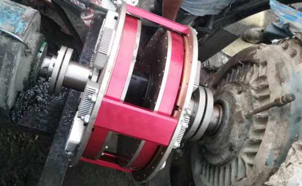
The conveyor magnetic coupling realizes the torque transmission from the motor to the load through the air gap between the copper conductor and the permanent magnet. The biggest feature of this technology is that there is no mechanical connection between the driving side (motor) and the driven side (load). Its working principle is that the rare metal oxide permanent magnet at one end generates a permanent magnetic field, and the copper conductor at the other end cuts the magnetic field lines in the permanent magnetic field to generate an induced magnetic field, and the two magnetic fields mesh with each other to form a magnetic connection, thereby generating torque. The schematic diagram of the structure of the conveyor magnetic coupling is shown in Figure 2.
Application
Coal No. 9 belt conveyor is DT II type, the belt width is 1200mm, the belt speed is 2m/s, the inclination angle is 36.5°, the horizontal single length of the belt is 130m, and the conveying capacity is 630t/h. According to the technical parameters of the No. 9 coal belt conveyor, the magnetic coupling was selected to replace the original torque-limiting hydraulic coupling, and was installed between the output end of the motor shaft and the input end of the reducer. Adjust the distance between the conductor and the magnetic block according to the actual needs, and finally achieve the required operating load of the belt conveyor and work according to the actual needs. The main technical parameters of the magnetic coupling and the original torque-limiting hydraulic coupling are compared in Table 1.
| Table 1 Comparison of main technical parameters between conveyor magnetic coupling and original torque-limiting hydraulic coupling |
|||
| Name and model remarks | Before modification | After modification | |
| Motor and reducer connection | Hydraulic Coupler | Magnetic coupler | |
| Motor (Y315M – 4/132 kW, RPM:1480 r/min) | unchanged | unchanged | |
| Reducer (DCY400 – 31.5 – IIN, transmission ratio:31.5) | Unchanged | Unchanged | |
| Mounting dimension of motor and reducer base | Unchanged | Unchanged | The brake wheel (Ф 400 mm) is redesigned, and the connection method of the shaft end is changed to the expansion sleeve type |
The same, the coking plant has no effect on the design of the conveyor magnetic coupler we provide.
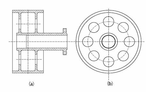
The structure and related dimensions have been improved, and the structure of the rear brake wheel has been improved.
The intention is shown in Figure 3 (a), (b).
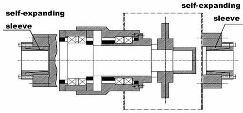
At the same time, the original key and elastic coupling connection are changed to self-expanding tight-sleeve connection, which achieves the purpose of convenient disassembly and assembly, and can shorten the time by more than half.
After the conveyor magnetic coupling replaces the hydraulic coupling, there is no mechanical connection between the motor and the reducer, so that the vibration of the conveyor belt drive drum side will not be transmitted to the motor side, and the vibration of the motor side will not be transmitted to the high-speed end of the reducer. At the same time, the amplification effect of vibration in the transmission process is also cut off.
When the coal is blocked and the bucket is overloaded, the magnetic coupler can automatically disconnect the torque transmission of the motor to the load. At this time, the motor runs with no load and the belt stops, thus eliminating the phenomenon of the conveyor belt breaking due to overload.
The peak value of the starting current is reduced by about 20% compared with the previous one, the peak duration of the starting current is shortened by 60%, and the instantaneous tension of the tape is reduced by 30%, thus greatly extending the service life of the tape and the motor. The magnetic coupling is simple in structure, easy to disassemble and assemble, and requires low centering deviation. After replacing the hydraulic coupling, it not only achieves the goal of maintenance-free, but also effectively solves the problem of environmental pollution caused by the leakage of the medium oil in the hydraulic coupling.
From the above analysis, it can be seen that compared with the original hydraulic coupling, the magnetic coupling has the following advantages: maximum allowable eccentricity; allowable pulsating load; transmission of motor output torque through magnetic field, no mechanical connection, which can effectively isolate vibration; Flexible starting, the current is reduced during starting; the speed of the load can be adjusted according to the system operating conditions; maintenance-free and easy to install; conducive to environmental protection. Table 2 shows the comparison of the use of conveyor magnetic coupling and hydraulic coupling.
| Table 2 Comparison of the use of magnetic coupling and hydraulic coupling | ||
| Project | Hydraulic coupling | Magnetic coupling |
| installation requirements | high | The allowable axial displacement is 1 mm; the allowable centering error is 2 mm. |
| Vibration reduction effect | better | Effective isolation, no mechanical connection reduce vibration effects by 85%. |
| Maintenance workload and cost | high | Maintenance-free |
| Overload protection | reliable | completely disengaged |
| energy saving effect | No obvious effect | Compared with the use of hydraulic coupling, the power consumption can be reduced by 10%. |
| soft start | better performance | Enables zero-load starting (non-contact torque). |
| structure | more complicated | Simple, with few components. |
| volume | Moderate | Small |
| precision | very low | very high |
| Speed range | minimum | 40% to 96% |
| environmental impact | larger | none |
Conclusion
This coking plant has used the conveyor magnetic coupling in the coal unloading and transporting system for more than a year. The production practice shows that no mechanical connection improves the start-stop performance of the system, and achieves the effects of vibration reduction, safety, reliability, energy saving and environmental protection.


