Table of Contents
Application of Magnetic Shaft Coupling in Rotary Drum Pulper
In this article, we talk about the magnetic Shaft Coupling in waste paper deinking.
As we all know, the drum pulper is very important equipment in the waste paper deinking and pulping production line. Through the rotation of the drum, the waste paper raw materials sent by the conveyor are continuously sheared and pushed forward. The drive system of the drum pulper is generally composed of a motor, a coupler, and a reducer. The drum pulper has a mild operation process and can use relatively poor raw materials to produce high-performance pulp. It is mostly arranged in waste paper sorting or stacking yards, and the production environment is harsh; There are many locking conditions, and various interlocking trips will inevitably occur occasionally, which usually lead to the accumulation of wet and dry waste paper at the bottom of the drum. In this case, when the drum pulper is started again, the starting current will be very large, which The drive system of the pulper is a huge test. As the connection part between the motor and the reducer, the reliability of the coupler determines the operating rate of the drum pulper. The common coupler is the hydraulic coupler. With the advancement of technology, magnetic shaft coupling appears.
Magnetic shaft coupling and hydraulic coupler
Working principle
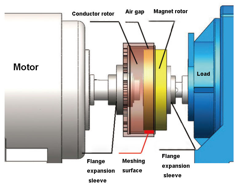
The magnetic shaft coupling is installed between the motor and the load and is connected with the motor output shaft and the load input shaft through the expansion sleeve coupling. The magnetic coupling is mainly composed of conductor components, permanent magnet components and flange expansion sleeves. The schematic diagram of its structure is shown in Figure 1. Wherein, the conductor assembly includes a conductor rotor and a conductor barrel, and is connected to the motor side; the permanent magnet assembly includes a permanent magnet rotor and a permanent magnet barrel, and is connected to the load side, and there is no rigid contact between them. Its working principle is: the motor starts to drive the conductor assembly to move, the conductor assembly and the permanent magnet assembly move relative to each other, the conductor assembly cuts the magnetic field lines, and eddy current is generated in the conductor, and the eddy current generates an anti-inductive magnetic field, which interacts with the magnetic field generated by the permanent magnet. , to achieve torque transmission between the two. Therefore, there is a contactless connection between the motor and the load, but the torque can be transmitted.
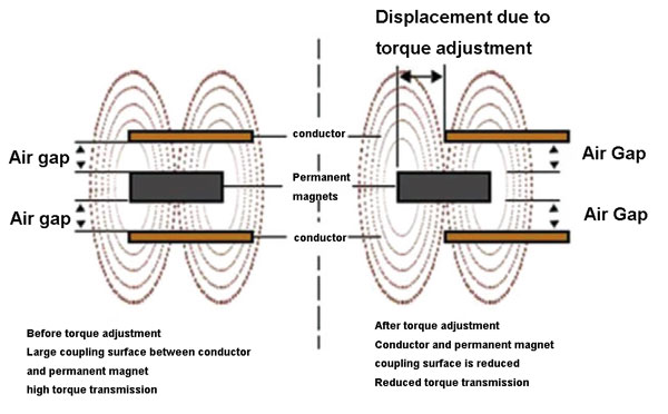
The magnetic shaft coupling is installed between the motor and the load to transmit torque, and the load speed change is realized by adjusting the magnetic field coupling area between the conductor rotor and the permanent magnet rotor. The larger the coupling area, the greater the torque transmitted through the magnetic shaft coupling, and the higher the load speed; the smaller the coupling area, the smaller the torque transmitted through the magnetic shaft coupling, and the lower the load speed, the schematic diagram is shown in Figure 2.
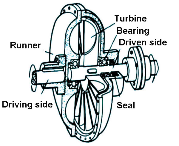
The pump wheel and turbine of the hydraulic coupler form a closed working chamber that can circulate the liquid. The pump wheel is installed on the input shaft, and the turbine is installed on the output shaft, as shown in Figure 3. Its working principle is: when the motor drives the input shaft to rotate, the liquid is thrown out by the centrifugal pump wheel. After this high-speed liquid enters the turbine, it drives the turbine to rotate, and transfers the energy obtained from the pump wheel to the output shaft. Finally, the liquid returns to the pump impeller, forming a cyclical flow.
Characteristic Analysis
Transfer efficiency
The magnetic shaft coupling uses an air gap to transmit torque, and the power loss mainly includes slip loss and mechanical loss, and the maximum efficiency can reach 98%. The losses of the hydraulic coupler mainly include hydraulic loss, mechanical loss and volume loss, and the mechanical efficiency is about 96%. The mechanical efficiency of the magnetic shaft coupling is slightly higher than that of the hydraulic coupler, and it can replace the hydraulic coupler in terms of mechanical efficiency.
Impact on the environment and equipment
Magnetic shaft couplings have no special requirements for the use environment. Large voltage fluctuation, high harmonic content, flammable, explosive, humid, high dust content, high temperature, low temperature and other places can be used; the whole device has no lubricating parts and does not produce any pollutants. When the magnetic shaft coupling is installed, it is connected through the expansion sleeve without changing the distance between the original motor and the reducer; after installation, it will not cause electromagnetic interference to the entire system. Due to the non-contact connection between the active rotor and the driven rotor, the vibration of the reducer side will not be transmitted to the motor side, and the vibration of the motor side will not be transmitted to the reducer side, which greatly reduces the installation accuracy requirements between the motor and the load. . Although the hydraulic coupler is also a non-contact connection, it does not solve the problem of installation accuracy between the motor and the load. It needs to be precisely aligned, and the alignment error needs to be less than 0.05mm, otherwise the equipment will easily vibrate out of tolerance. In addition, hydraulic oil is easy to leak and pollute the environment.
Daily maintenance
The magnetic shaft coupling is connected by an expansion sleeve, which is easy to install and less time-consuming; after being put into use, the fault is easy to diagnose, and the maintenance workload is small; there are no wearing parts. The vibration problem of the hydraulic coupler causes the load and motor bearing to wear a lot, and the replacement cycle is short; the hydraulic oil, as a consumable, needs to be replaced periodically; and it generally adopts the heating installation method, which is difficult to assemble and disassemble, and the replacement takes a long time.
Service life
According to reliability theory, the more components a system or device uses, the lower the reliability of the system. Because any component with low reliability in the system will affect the reliability of the entire system, which is similar to the “cask theory”, that is, the reliability of the system is determined by the component with the lowest reliability in the system. It can be seen from this that, when the system or device achieves the same function, the fewer the number of components used, the lower the failure rate of each component, and the higher the reliability of the system. The magnetic shaft coupling is mainly composed of two components, in which the failure rate of the conductor rotor and the permanent magnet rotor is almost 0, while the number of components of the hydraulic coupler is much larger than this number, and the reliability is relatively low. At this stage, the service life of the hydraulic coupler is about 8 years, and the service life of the magnetic shaft coupling is about 20 to 30 years.
Cost
According to the current purchase price, the magnetic shaft coupling is about 5 times that of the ordinary domestic hydraulic coupler.
In summary, the magnetic shaft coupling has advantages over the hydraulic coupler in the use environment, installation accuracy, routine maintenance and service life, and the mechanical efficiency can meet the requirements of high mechanical efficiency of the hydraulic coupler. The application of the coupler on the drum pulper goes a step further introduce.
Application of magnetic shaft coupling on drum pulper
Project background
The original transmission connection method of the drum pulper of the waste paper pulping production line of Company A is the connection of motor + hydraulic coupler + reduction box. Due to the limitations of the hydraulic coupler design, combined with the actual operating conditions of the drum pulper in recent years, the power changes caused by repeated trips and restarts, continuous pulp full shutdown and increased production have resulted in more than a year of time. (February 2016 to July 2017) 3 sets of hydraulic couplers were continuously damaged in the interior. The hydraulic coupler has high technical requirements and is imported from abroad, with high procurement cost and long time. Multiple damages not only affect the continuous operation of the pulping line, but even cause unplanned downtime of the paper machine line. Therefore, the failure of the hydraulic coupler has become a bottleneck restricting normal production, which needs to be solved urgently. The project compared the characteristics of the magnetic shaft coupling and the hydraulic coupler, and chose to use the magnetic shaft coupling to transform it.
Selection of magnetic shaft coupling
According to the different cooling forms, the magnetic shaft coupling is divided into two types: air-cooled and liquid-cooled; according to the configuration of the speed control mechanism, it is divided into two types: without speed control device and with speed control device; according to the structure of the magnetic shaft coupling, It is further divided into: disc structure type, single-cylinder type and double cylinder type.
The company is located near the estuary of the Pearl River. In winter, there is a salt tide caused by seawater backflow. The drum pulper to be transformed is located in the waste paper sorting yard, and the site environment is dusty. The original drive system is equipped with a 1350 kW motor. High voltage motor, no frequency conversion device. The equipment parameters of the drum pulper are shown in Table 1, and it is required to be able to cope with overload startup and frequent startup; due to the limitations of the on-site installation environment and time, it is required not to change the basis of the original equipment, nor to change the original gearbox and motor. position; when selecting the model, it should be mainly considered from the simple structure and more stable operation.
| Table 1 Equipment parameters of drum pulper | |
| Device name | Drum pulper |
| Motor | ABB AMA 500L4A BAS |
| Motor rated power, speed | 1350 kW,1492 r/min |
| Dimensions of motor shaft and gearbox input shaft | Ø140 mm,Ø140 mm |
| Maximum outer diameter of hydraulic coupling | Ø1150 mm |
| Distance between motor shaft end face and motor housing | almost 250 mm |
| Distance from gearbox input shaft end face to gearbox bearing cap | almost 250 mm |
| The distance between the motor shaft and the input shaft of the gearbox | almost 257 mm |
| The center height of the motor shaft and the input shaft of the gear box | 610 mm |
Choice of cooling form
The ambient temperature is a very important factor affecting the magnetic shaft coupling. The magnetic shaft coupling itself generates a large amount of heat. If the cooling method is not selected correctly, the magnetic shaft coupling will operate at a very high temperature for a long time, and the magnet may be demagnetized, resulting in permanent magnetism. The magnetic shaft coupling cannot properly drive the device. Therefore, factors such as the site environment, the heat generation of the magnetic shaft coupling itself, and the economy need to be fully considered. There are two common cooling methods for magnetic shaft couplings, see Table 2 for details. Air-cooled products rely on the rotation of the equipment to generate air flow for natural cooling. Liquid-cooled products require an external cooling medium for cooling and cooling; air-cooled products are suitable for general environments, but some harsh The cooling effect may be insufficient in the environment. The liquid-cooled type can cope with harsher environments through precise control methods such as adjusting the coolant flow and controlling the temperature due to the external coolant and supporting control devices. From the perspective of product size and maintenance, the air-cooled type The product is generally simple in structure and small in size, and only needs to be blown regularly for maintenance; liquid-cooled products have more complex structure and relatively large size, and need to be equipped with a separate set of cooling devices with coolers, pumps, control systems, etc., and equipment components Many, many failure points, large maintenance, high cost. This transformation project chooses an air-cooled magnetic shaft coupling. First, although the application environment of this magnetic shaft coupling is in the waste paper sorting field, the air circulation is good, and the cooling capacity of the air-cooled type can meet the demand; although the liquid-cooled type has better effect , but in addition to the above-mentioned factors of higher cost, due to the occasional salt tide in the company’s location, the water contains high chloride ions. If you want to ensure that the external cooling system is not corroded by chlorine and operates normally, you need to choose a The heat exchanger of anti-chlorine corrosion material – titanium plate heat exchanger, which further increases the investment cost.
| Table 2 Comparison of air cooled and liquid cooled magnetic shatf coupling |
||
| Contrast | Air-cooled permanent magnet coupler | Liquid-cooled permanent magnet coupler |
| cooling method | The equipment rotates to generate air flow for natural cooling | External cooling medium cooling |
| cooling medium | Air | Coolant (cooling water, cooling oil) |
| cooling effect | Generally adequate, but insufficient cooling in some environments | Precise control by adjusting coolant flow, controlling temperature, etc. |
| product size | Simple structure and small size | Complex structure and relatively large size |
| maintenance | blow dust regularly | A separate set of cooling devices (cooler, pump, control system, etc.) are configured, with many components, more equipment to be protected, many fault points, large maintenance, and high cost |
Selection of the configuration of the speed control mechanism
The magnetic shaft coupling can achieve a certain speed regulation effect by adjusting the mesh size, but the magnetic shaft coupling equipped with the speed regulating mechanism can control the speed more accurately, basically achieving the purpose of replacing the frequency conversion device. Therefore, it should be selected from the main needs to be satisfied. This project chooses a magnetic shaft coupling without a speed regulating mechanism. First, the motor is an ordinary high-voltage motor without a frequency conversion device; second, power-saving and speed regulation are not the main requirements to be met; third, it can be adjusted by adjusting the mesh size in the later stage. Adjust the speed slightly.
Choice of structural form
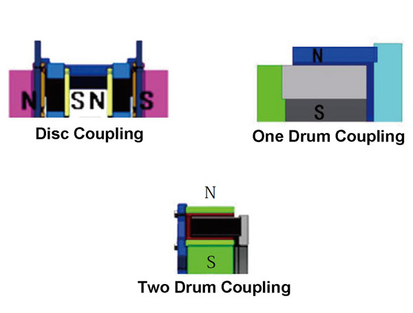
The three structural forms of the magnetic shaft coupling are shown in Figure 4. From the structural point of view, the conductor rotor of the disc structure is composed of two conductor discs, which has a complex structure and low magnetic field utilization efficiency. The single-cylinder type conductor rotor consists of one conductor cylinder (outer cylinder), which can only use the magnetic field on one side of the permanent magnet rotor for torque transmission, and the magnetic field utilization efficiency is low. The double-barrel conductor rotor consists of two conductor barrels (inner barrel and outer barrel). When the permanent magnet rotor and the conductor rotor are effectively coupled, the conductor rotor can make full use of the magnetic fields on both sides of the permanent magnet rotor for torque transmission, and the magnetic field efficiency is higher than high. Under the same load torque output requirements, in order to achieve the same torque transmission as that of the double-barrel magnetic shaft coupling, the disc structure type and the single-barrel magnetic shaft coupling can only be solved by the following methods: 1. Increase the conductor rotor and the diameter of the permanent magnet rotor to increase the effective coupling area of the magnetic field to meet the output of the load torque; ② increase the width of the conductor rotor and the permanent magnet rotor to increase the effective magnetic shaft coupling area and realize the output of the load torque. From the perspective of cost, the double-cylinder type is the most expensive, the disc-type structure type is the cheapest, and the single-cylinder type is between the two. How to choose should be based on actual needs and purposes. The purpose of this project is to solve the problem of heavy-load starting. In order to achieve the same high torque output, the disc structure type is the heaviest, the single-cylinder type is the second, and the double-cylinder type is the lightest. The original hydraulic coupler is made of aluminum alloy and is light overall; therefore, from the perspective of minimizing the load on the motor and gearbox and solving the problem of heavy-load starting, a double-barrel magnetic shaft coupling should be selected.
| Table 3 Equipment parameters of magnetic shaft coupling | |
| name | Data |
| model | SPRO1000 |
| cooling form | Air-cooled |
| speed control mechanism | none |
| structure type | Double barrel type |
| Dimensions | Outer diameter≤Ø1000 mm Width≤620mm |
| Weight | ≤345kg |
| The distance between the motor shaft and the shaft end of the gearbox | 257 mm (unchanged) |
| Connection Type | Expansion connection |
| Operating temperature | -20~60℃ |
To sum up, the air-cooled double-barrel magnetic shaft coupling without a speed regulating mechanism is selected for this transformation project. The parameters of the magnetic shaft coupling are shown in Table 3, which match the parameters of the pulper equipment. There is no need to change the original equipment foundation, and the reduction box and the motor keep their original positions.
Installation of magnetic shaft coupling
Check the installation conditions
Check the ambient temperature to meet the operating temperature requirements. Stop the system and power off according to regulations. Remove the original hydraulic coupler, check the radial runout and end face runout of the motor shaft and gearbox shaft, both of which need to be ≤0.05mm. Check the axial endplay of the motor and the load, and the allowable value of the axial endplay of the ball bearing should be in accordance with Table 4. Pry inspection, use a crowbar to pry the motor shaft in the radial direction, mark the meter on the motor shaft, keep the motor body still, check the motor shaft runout; check the load shaft runout in the same way, the runout of the two axes should be ≤0.1mm. If the above checks cannot be satisfied, check the original motor and load, check the cause of the jump, and install a magnetic shaft coupling after solving it.
| Table 4 Allowable value of axial endplay of ball bearing | |
| Shaft diameter/mm | Axial endplay/mm |
| 30~50 | 0.12~0.22 |
| 50~65 | 0.15~0.28 |
| 65~80 | 0.20~0.35 |
| 80~100 | 0.25~0.50 |
| 100~120 | 0.30~0.55 |
Inspection before installation
Verify that the load is in the same direction as the magnetic shaft coupling rotation. Remove stickies, burrs, and dirt from motors, load shafts, and keyways, and keep them clean and dry. Measure the diameter of the motor, the load shaft and the inner diameter of the magnetic shaft coupling 2 expansion sleeve to ensure smooth installation. Check the key size to make sure it fits smoothly.
Install the conductor rotor
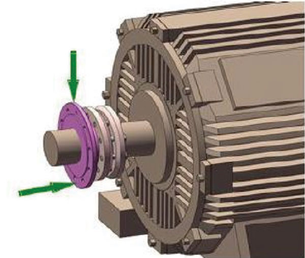
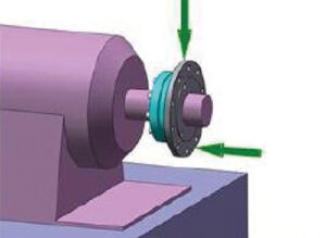
Loosen the expansion sleeve and motor shaft sleeve bolts, then remove them, but the expansion sleeve on the motor shaft sleeve, and install it on the motor shaft together, tap the end face of the shaft sleeve with a tool until it meets the requirements of the drawing. Tighten the bolts of the expansion sleeves, initially tighten them, and measure the runout on the outer edge of the sleeve and the circumference of the sleeve, as shown in Figure 5, and continuously measure and adjust to ensure that the runout is less than or equal to 0.1mm. Take the remaining part of the conductor rotor and install it on the motor bushing, so that the motor bushing and the driving disc are tightly fitted, and then tighten the bolts.
Install the permanent magnet rotor
Loosen the expansion sleeve and the bolts of the load shaft sleeve, then remove them, put the expansion sleeve on the load shaft sleeve, and install it on the load shaft together, and tap the end face of the shaft sleeve with a tool until it meets the requirements of the drawing. Tighten the bolts of the expansion sleeves, initially tighten them, and measure the runout on the outer edge of the sleeve and the circumference of the sleeve, as shown in Figure 6, and continuously measure and adjust to ensure that the runout is less than or equal to 0.1mm. Take the remaining part of the permanent magnet rotor and install it on the load bushing, so that the load bushing and the driven disc are tightly fitted, and then tighten the bolts. It is recommended to use thread tightening glue for the bolts and finally tighten the expansion sleeve bolts.
Combined conductor rotor and permanent magnet rotor
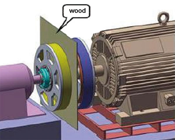
Hoist the motor together with the conductor rotor on the motor foundation, so that the conductor rotor and the permanent magnet rotor are as close as possible. In order to prevent collision or suction during the hoisting process, a wooden board can be placed between the two rotors in advance, as shown in Figure 7. Remove the wooden board, adjust the position of the motor with the motor adjusting screw, couple the conductor rotor and the permanent magnet rotor to the size required by the drawing, and adjust the radial clearance of the two rotors evenly, requiring the clearance deviation everywhere to be ≤0.5mm. During the adjustment process, be careful not to collide the conductor rotor and the permanent magnet rotor. After adjusting the motor position, lock the motor.
Install the protective cover
Put the protective cover on the magnetic shaft coupling, adjust the position of the protective cover to ensure that the protective cover does not come into contact with the two rotors, and try to adjust the distance between each internal position and the distance between them to be relatively uniform, and fix the protective cover.
Debugging of magnetic shaft coupling
Check the installed magnetic shaft coupling to ensure that all parts are well connected and the protective cover is not in contact with the magnetic shaft coupling. Paste reflective paper on the motor and load shaft for speed measurement. Clear the debris on site and open the system damper or valve to the maximum. Personnel evacuated to a safe location. Start the motor according to the normal process of equipment startup, and then detect the motor, load vibration, speed and temperature after running smoothly, and perform intermittent multiple sets of measurements. Load and motor vibration value ≤ 0.05mm, conductor rotor outside temperature ≤ 130 ℃. If an abnormality is found, stop the inspection in time.
Magnetic shaft coupling maintenance
The following checks should be done before each startup: check whether the protective cover is loose and whether it is in contact with the magnetic shaft coupling; check whether there are foreign objects or items that are easily blown up around the equipment.
Daily inspection: check the outside temperature of the magnetic shaft coupling ≤ 130℃, check the vibration value of the motor and load ≤ 0.05mm, and check when abnormal shutdown occurs. Equipment maintenance: Remove the protective cover every half a year and use compressed air to purge the dust on the inner and outer heat sinks and the protective cover; check whether the connecting bolts are loose, including the bolts of the expansion sleeve; check whether there are any signs of wear between the rotors, Make sure the rotor clearance is even. If the temperature is too high, it is easy to cause the magnet to demagnetize. It is recommended to keep the operating temperature as low as possible. Measure the magnetic force of the magnet at regular intervals. If there is a significant drop, the magnetic shaft coupling should be removed and the magnet should be replaced.
The effect after transformation
The main parameters of the drum pulper before and after reconstruction are shown in Table 5. From Table 5, it can be seen that the active power of the motor at normal startup of the drum pulper is reduced from 505.22 kW before the transformation to 301.75 kW after the transformation; kW is reduced to 1117.54 kW after the retrofit. The vibration measurement speed value of the drum pulper gearbox was reduced from 5.8mm/s before the transformation to 1.0mm/s after the transformation. When the drum pulper is normally started, the load start-up and the vibration value of the reduction box are significantly lower after the transformation than before the transformation.
| Table 5 Comparison of main parameters before and after transformation | |||||
| Motor | Power/kW | normal starting power | Load starting power/kW | Vibration speed/mm·s-1 | Failure times/Year |
| ABB AMA | 1350 | 505.22 | 1860.13 | 5.8 | 2 |
| 500L4A BAS | 1350 | 301.75 | 1117.54 | 1 | 0 |
Since the completion of the transformation of the magnetic shaft coupling in October 2017, the company’s drum pulper has not been shut down due to the failure of the transmission coupler. The production loss caused by unplanned downtime not only ensures the stability of production, but also creates benefits for the enterprise.
Conclusion
The magnetic shaft coupling is a new transmission connection method with a simple structure, safety and reliability, and low maintenance. The application in the waste paper pulping drum pulper of Company A shows that it is used in motor soft start, overload protection, and vibration elimination, It has good performance in overload startup and other aspects, and it is worth continuing to study and apply in some working conditions that need to solve such problems.

