Conveyor Belt Magnet Coupler in Coal Preparation Plant
In this post, we talk about how a super large coal preparation plant uses the conveyor celt magnet coupler to improve efficiency and save cost.
The super-large coal preparation plant processes 12 million tons of washed raw coal every year. In order to save energy and improve efficiency, the coal preparation plant started with the improvement of the transmission device, and took the lead in researching and analyzing the transmission device of the C301 belt conveyor, and found that the existing motor during the engineering design of the transmission unit, the power margin is large, and the rated power of the motor is more than 30% higher than the actual demand. There are problems such as high energy consumption, large waste of resources, poor system safety, and serious wear of system components, which seriously restrict the improvement of system efficiency.
Analysis of existing rotating devices
The existing rotating device is a traditional hydraulic coupler connection method, which adopts an asynchronous motor to connect the reducer, the hydraulic coupler, and the transmission structure of the driving drum, and centrally controls the operation of each motor on the line through the centralized control room. There are the following problems: low power factor, large energy consumption, and large starting current; large capacity of the power supply transformer, unstable operation during startup, and certain impact on the tape; large mechanical loss of the front-end reducer, low transmission rate, low operating efficiency, and energy It consumes a lot and does not meet the requirements of energy saving and environmental protection; the structure of the transmission device is complex, the daily maintenance workload is large, the installation and disassembly are difficult, and the operation and maintenance cost is high; improper maintenance of the hydraulic coupling with oil as the working medium can easily cause fire; the overall transmission device The service life is short, generally need to be replaced after 2 to 3 years. In view of the above problems, in order to improve the efficiency of the transmission device and reduce the burden on the reducer, the most effective method is to improve the hydraulic coupling.
Advantages of Magnetic Couplers
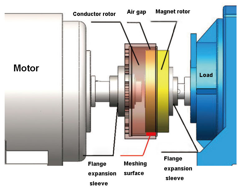
The magnetic coupler transmission is a transmission mode without mechanical connection. Its working principle is to realize the torque transmission from the motor to the load through the air gap between the conductor and the magnetic rotor. Its advantages are as follows: the energy saving effect is remarkable, The air gap can be adjusted to change the speed, and the energy saving rate can reach 10% to 50%; the soft start with buffer reduces the inrush current of the motor and prolongs the service life of the equipment; it can tolerate large errors in installation, which greatly simplifies the installation and debugging process; With overload protection function, it improves the reliability of the entire motor drive system; maintenance-free, no bearing, no need to add lubricating oil or grease; no wear parts, no material deterioration problem; design life of 30 years, long service life; volume Small, easy to install, easy to carry out system transformation; simple structure, suitable for various harsh environments, does not produce pollutants, and meets the requirements of green products.
Transformation scheme of belt conveyor transmission
This time, the transformation test of the C301 belt conveyor transmission was carried out. According to the requirements of technical parameters, a large amount of information was consulted, and a torque-limiting magnetic coupler was finally selected. Its parameters are shown in Table 1, and the structure diagram is shown in Figure 1.

| Magnetic Coupler Parameters | ||
| Category | Parameter | Remarks |
| Power range | 0 to 1 000 kW | |
| Speed range | 0 to 3 600 rpm | |
| Torque range | 0 to 12 000 N·m | |
| Noise | 85 dB | |
| Slip | 2% ~ 4% | |
| Distance between shafts | 100 to 300 mm | |
| Over torque protection | 2.5x | Motor Torque |
Preparations before installation
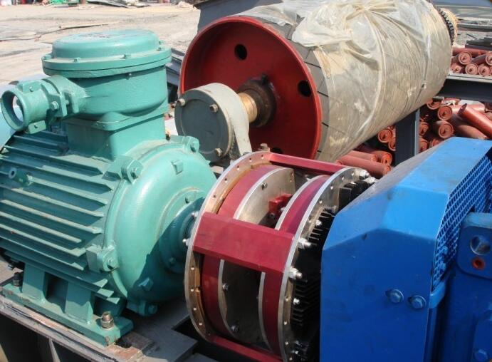
Check the axial movement of the motor and the load, which shall not be greater than 0.76 mm, the installation diagram is shown in Figure 2.
Mounting flange
Check the matching dimensions of the motor and load flange before installation. axis must
Deburring, degreasing, cleaning, drying. The roughness of the shaft and flange mating section should reach 1.6 to 3.2. Draw a mark on each shaft according to the length of the corresponding flange. The recommended maximum radial clearance between the shaft and the flange is shown in Table 2. In order to improve the dynamic balance of the motor and the load shaft, install a half key in the keyway, and check that the half key does not protrude from the circumferential surface of the shaft.
| Table 2 Recommended maximum radial clearance for shaft to flange fit | ||
| Shaft diameter | Big radial gap | |
| From | To(include) | |
| 28 | 49 | 0.038 |
| 49 | 120 | 0.051 |
| 120 | 180 | 0.076 |
Install the magnetic drive
Mount the magnetic rotor component on the load shaft, coupling the motor method
Blue and conductor rotor parts.
Remove the drive set screws
Remove the set screws on each side of the drive and store away from the drive.
Alignment of rotor parts of magnetic drive
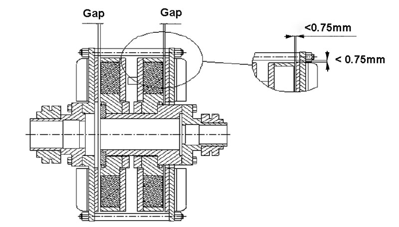
The purpose of centering of rotor parts of magnetic drive is to make the air gap between the magnetic rotor and the conductor copper plate equal, and the air gap value is equal at each position (error < 0.75mm), and the schematic diagram of the air gap of the magnetic actuator is shown in Figure 3. Figure 3 Schematic diagram of the air gap of the magnetic actuator
The operation procedures for the alignment of the rotor components of the magnetic drive are as follows:
1) Angular, axial alignment: measure the distance between the conductor rotor and the end face of the magnetic rotor in the drive. Radial Alignment: Measure the distance between the outer circle of the magnetic rotor and the air gap plate.
2) Complete alignment by moving the motor, using the top wire of the motor foot, and the gasket of the motor foot. Alignment is complete when all measurements meet the requirements of Figure 3.
3) Tighten all motor anchor bolts.
4) Rechecking the alignment Radial alignment and tightening the motor anchor bolts may change the angular and axial alignment. If the alignment data is incorrect: Loosen the motor anchor bolts and repeat step 2 until the alignment is correct.
System debugging
Prepare for commissioning:
① Confirm that the conductor rotor set screw has been removed;
② Jog the motor to confirm whether the steering is correct;
③ Install soundproof cover or protective cover;
System test run:
① Start the motor;
②Measure the vibration of the motor and the load;
③ Pay attention to whether there is any abnormal sound during operation.
Apply the effect
Since the use of the magnetic coupler, the transmission efficiency of the 301 belt in the coal preparation plant has been significantly improved, and the hourly coal volume has also increased, and the energy saving and environmental protection effect is remarkable. The torque limit can realize automatic stall protection, improve the reliability of the entire motor drive system, and is easy to maintain. At the same time, the operating cost of the system is reduced, and the benefit of the coal preparation plant is further improved: After the 301 belt is transformed by the transmission device, the transmission efficiency is increased by 10%, the power consumption is reduced by 20%, and the annual electricity cost can be saved by 600,000 yuan; due to the use of magnetic coupler The lubricating oil is no longer used after the device, and the annual cost of lubricating oil is reduced by 100,000 yuan; in terms of equipment maintenance and repair, it is relatively simple, and the annual maintenance cost is reduced by 300,000 yuan; the annual comprehensive efficiency is expected to be 1 million yuan. It can be seen that the transmission mode without mechanical connection using the magnetic coupler after the transformation has obvious advantages over the traditional hydraulic coupling transmission mode.


